We have Power
Electrical power that is. But first to finish up the garage heater upgrade details as promised from the last post. Cause I know how many of you are just itching to know all about my garage heating!
As I mentioned last post I was adding a digital thermostat to the heater so it didn’t run all the time. To accomplish that I had to add a few things, 1) A digital thermostat 2) a 24V transformer and 3) a single pole 24v controlled contactor/relay. Originally, I was going to add the additional contactor and the transformer in a separate J-Box on the wall but after looking at the space in the bottom of the heater I figured out I could move the wiring tap and then I would have space to fit in the transformer and the contactor. In the pic below you can see the transformer and the contactor (the 2 black things on the right side of the pic).
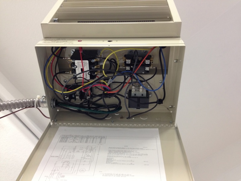
I had to add those because a regular digital thermostat uses 24V to control your normal household heater, A/C. This unit however is 240V with just a basic thermostat that controlled the bigger contactor but it did it via 240v. Well I couldn’t send that down the wall to the digital thermostat over 22 gauge wire. Well I could have but this would have been a far different post with pictures of fire trucks, etc. Smartly deciding not to go that direction the first thing was to remove the basic thermostat and replace it with the single pole contactor but one that’s controlled by 24v. Then I added the 240v/24V transformer. Wired that to the heater control on the digital thermostat and it controls the new contactor in place of the original thermostat. And blamo it all works and I now have a nice toasty 67º in the garage over the weekend but during the week I have the thermostat programmed to let it drop to 55º. Saves a bunch of power, I know this because I was watching the power meter when the heater was on and I didn’t know they could spin that fast. 😮

Feeling pretty proud of myself I got back to the car. Well I pretty much wrapped up all the wiring with a few diversions that had to be taken care of and one minor exception. I had to finally focus on the parking brake since I was modifying it from the design and the mod put it right where the positive battery cable runs from the battery to the starter. I’ve decided to mount it on top of the tranny tunnel as opposed to the stock location which is on the passenger side of the tranny tunnel. I don’t like that look, you have to reach all the way over to it and that could be difficult when you have the full 4 point harness on. So to the top of the tranny tunnel it goes. Also since I have the midshifter on the tranny it moves the shifter forward creating extra space for it.
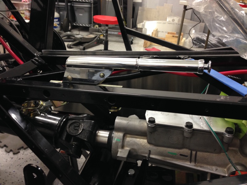

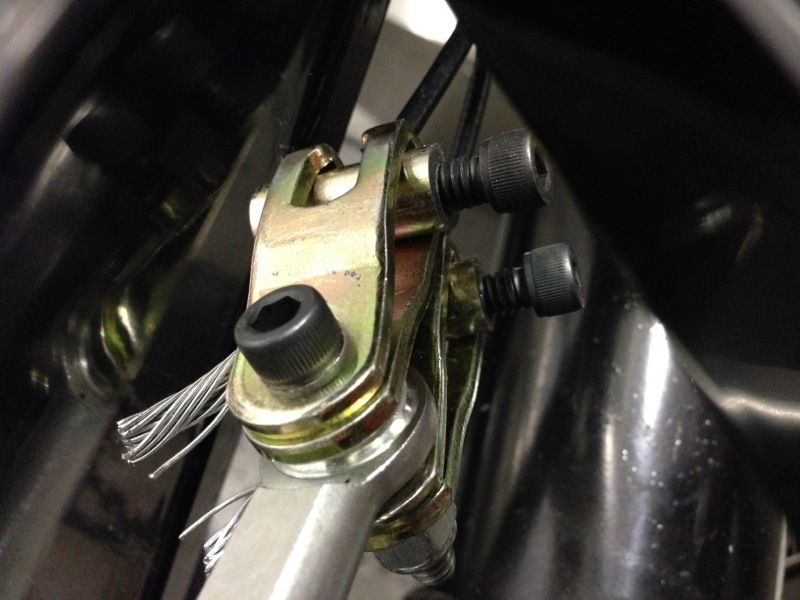
In the first pic above you can see the shifter handle installed on one of the 3/4 square tubes the forms the top of the tunnel. The second pic above shows the linkage from the handle to the 2 cables that go to the rear brakes. I had to fabricate 2 cable stays as the original cables were too long and I had to cut them. This presented an issue since they had factory formed stays on the ends and I needed to come up with a way to trap them in the bracket. I ended up taking piece of steel rod about 1″ long and first drilling a hole cross ways for the cable to through it perpendicularly. Then I drilled another hole length wise in the rod until it intersected with the first hole and tapped it. Ran a hex head screw into the tapped hole and then trapped the cable in the rod, inside the bracket. You can see them in the pic below. Yes you can buy the same thing somewhere and I looked but couldn’t find any so I just made some. It was fun. With that done I was able to figure out that I needed to rerun the battery cable down the driver side of the tunnel and you can see it moved in the first pic above. (the observant ones will notice the drive shaft is also installed. I put that in so I could fit the drive shaft safety loop and make sure it doesn’t interfere with the park brake either.)
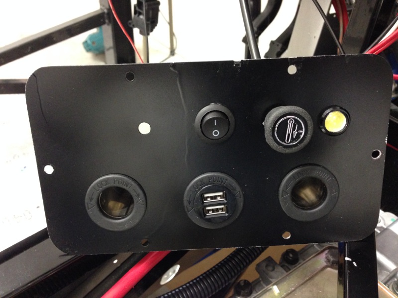
An additional item I had to take care of was my power panel. I’ve also created a plate that will go under the dash and close most of it in. In the center of it I’ve cut an opening for an access panel to get to the Ford PDU (Power Distribution Unit) for the engine. I decided that panel would also be a great place to put a couple of power ports, 2 USB ports, a courtesy LED light and the 2 dials, one controls the dash light dimming and the other controls the electric valve for the heater. You can see it below with everything installed expect the dash dimmer dial. And for those of you who notice the nice paint runs on the panel that’s a lesson learned of patience and not trying to spray paint in the wind. I’ll be taking the panel apart and sanding it down and repainting it again. This time without the runs. The switch in the center controls the courtesy lights. There are 3, one on this panel (the yellow dot on the right) and then one over each of the foot wells. For a rather small LED they kick out a nice bit of light. This whole panel will be tucked up under the dash essentially hiding these controls and allowing me to keep the dash clean with all the same style toggle switches.
The next thing I had to do was wire up the seat heaters but I ran into a small problem with that. While not a wiring problem what I needed to do was mount the drivers seat since it’s going to be on a slider for adjustment. I needed to do that so I could set the wiring for the heaters and figure out where I wanted the wiring to go from the seat to the car. I ran into a small problem just as I was about to drill the holes in the floor when I realized that the inside rails were right over the main 4″ chassis tube and I could mount into that. I need to rethink that part. So I set that aside other than adding the circuits to the fuse panel and I’ll figure out the runs once I figure out the seat mounting.
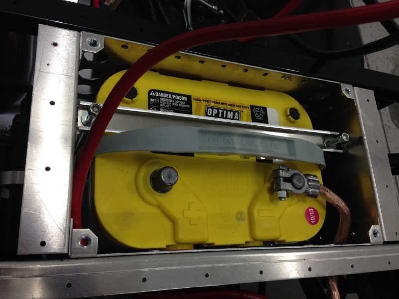
With all of that out of the way I was then able to move onto testing the electrics. First thing I did was check all the connections and verify all the grounds were tight. I then used my multimeter to confirm continuity between all the grounds, once i did that I then checked all the positive connections and confirmed continuity for those as well.I couldn’t do all of them since some of them are switched by the ECU and keyless start. Next thing I did was confirm there were no direct shorts between positive and ground. With that confirmed I pulled all the fuses and installed the battery.
With the battery installed I then placed an amp meter between it and the positive cable. I did get a click of one relay which initially caused me to jump as I wasn’t expecting anything to be hot. I soon realized it was the relay in the keyless system that has to have power all the time so the keyless part works. DUH! With the current draw at nearly zero I went ahead and connected the positive cable to the battery and no enormous blue arch incurred. Whew! I really didn’t expect there to be but I’ll admit in the past I didn’t expect a blue arc and got one anyways, another story for another time. Next step was to start adding fuses back into the panel and testing each circuit. First ones up were parking lights, brake lights, hazards, turn signals, head lights (opps found a problem), brights, heater blower, wiper circuit and gauges. Only problem so far are the headlights. I made a slight error in the rewire and right now they would essentially be on all the time, like day time driving lights. With the only real problem being they would be on ALL the time, even when the car is shut off and not running, well at least till I drained the battery. Simple fix though, just have to remove one wire on the relays and move one. Next and final check will be engaging the ignition. I won’t actually turn the engine over as it currently has no oil in it and has been sitting for at least 6 months. I’ll save that test until after it’s re-installed.
That’s pretty much the next step, I’ll solve the seat mounting problem, change a couple of connectors I don’t like and then pull the engine out and start permanently mounting the panels. Once those are mounted the engine will go back in for the final time. Stay tuned, it’s getting exciting and if I stay on track i’m hoping for a first engine start sometime in March.
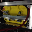
good choice on the Optima Yellow Top. I have been using that in my truck for about 8 years now and am very happy with it’s ability to drive high demand devices like my dual 15″ electric fans and 2000 watt stereo
Exciting update, and want to connect on the garage heater details with you. Can’t wait to come see the car in person!
Wiring and batteries can be a challenge but for an engineer like you it should be a snap.
Best
Randy,
Very good update and so cool seeing things come together…especially in a “warm” garage.
Build on!
mark….