Getting Hosed.
No not in the bad way. Last weekend before taking off to Atlanta for SCTE EXPO I got a chance to run the fuel lines and some of the fuel hoses. As for the hoses I’m running Braided Stainless Steel hoses to go with the Stainless Steel hard lines. If you have been following the build you’ve heard me talk about them before. All of the fuel line fittings will be the 37º AN-6 fittings. So to start I ran the hard lines first. The pic below shows the 2 lines running along the rear down tube on the passenger side. This is right behind the passenger seat but on the outside of the car in the wheel well. You can see one of the cockpit panels on the right. On the left side you can see the differential. The lines run underneath the car along one of the main chassis tubes up to the front and into the engine bay. I haven’t finished running the lines on the engine side as I need to have the engine in place to make sure everything clears. In case you’re wondering why there are 2 lines it’s because the system I’m running requires a supply line to the engine and then a return line. The return line is so that the fuel pressure regulator can maintain the proper pressure under low demand and return excess fuel back to the tank. Both of these lines will be connected to the pressure regulator.

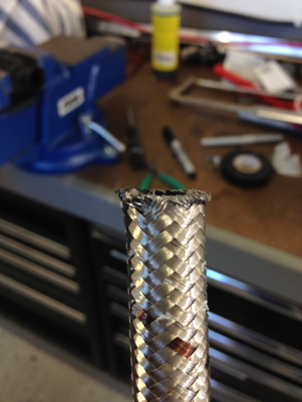
So the next step was to start making the hoses. The hoses come in whatever lengths you want and then you get whichever fittings you need. In the pic below you can see the cut end of the hose. Cutting this stuff is a process in itself. Due to the braid you can imagine how easy it is to fray this into a crazy mess. The trick appears to be to tightly wrap the hose with tape and then use a fine tooth 32-tpi hacksaw to cut it off. Taking your time and working your way around the hose is important as well. Wearing gloves is also recommended, I have the holes in my finger tips to prove my point.
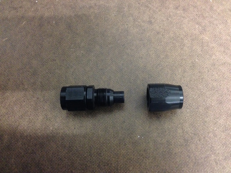
Next is getting the fitting ready to go on the hose. The pic below shows the fitting with the collar removed, the collar is on the right. This collar will have the hose installed from the right hand side. It will then screw onto the fitting on the left side of the pic. You can see the tube that will go into the hose. What’s hard to see is that tapered part of the fitting just to the right of the threads is actually a cutter and there is a gap between it and the tubing part. It will cut into the hose and once the collar is screwed on it will lock the hose into place.
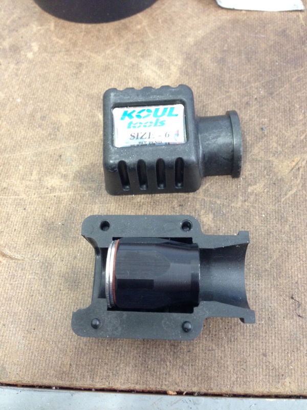
Now getting that hose with all those really sharp stainless steel fibers into that collar can be a real PITA. Fortunately some genius came up with a really cool tool to help with that and he even called it the Koul Tool. You can see the collar in the tool and you can see how the funnel on the right hand side guides the hose and braid right into the collar. For those of you who have asked me about needing any special tools, well this is one of them. It’s not really needed as you can do it without this tool but I think it’s probably the best $30 piece of plastic I’ve bought. Makes it real easy.
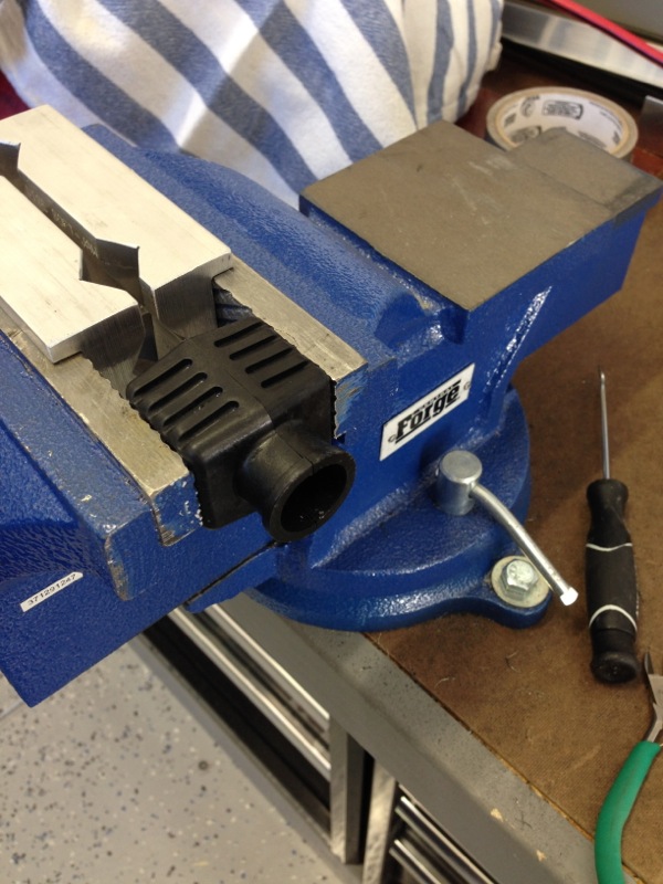
Once you have the collar in the tool you lock it in the vise and you twist the hose into the collar.
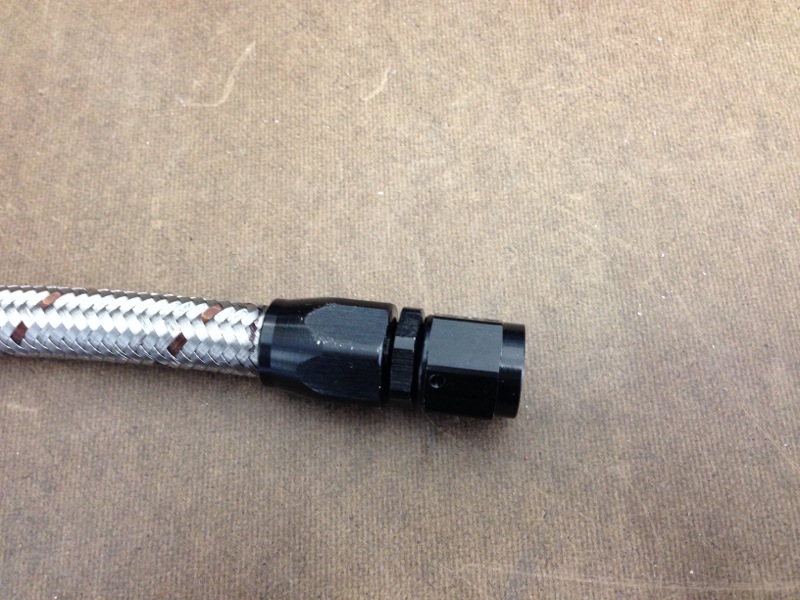
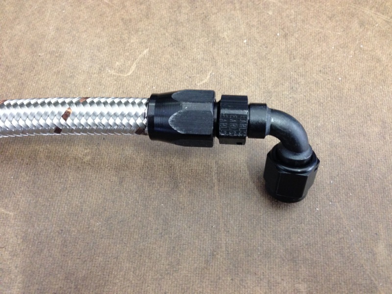
And this is what the completed part looks like after you screw the collar onto the fitting. Mating the 2 does take a bit of work as it is a very tight fit. You also have to pay attention to how far the hose backs out of the collar. If you look closely at the pic you can see the line I drew on the hose with a Sharpie just to the left of the bottom of the collar. I drew this before I started screwing the 2 parts together. If the hose moves more than 1/16 of an inch you have to redo it as it won’t hold the pressure. The first pic is a straight fitting and the second is a 90º fitting.
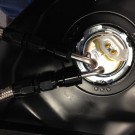
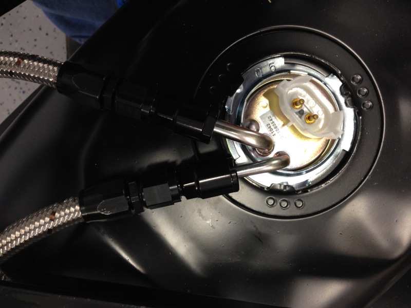
And these are the completed and installed hoses. These 2 hoses are on the gas tank, the one on the bottom is the return line and comes directly back from the regulator in the engine bay, the one the right goes to the fuel filter. In case you’re wondering the fuel pump is inside the tank and that’s what that electrical connector is for.
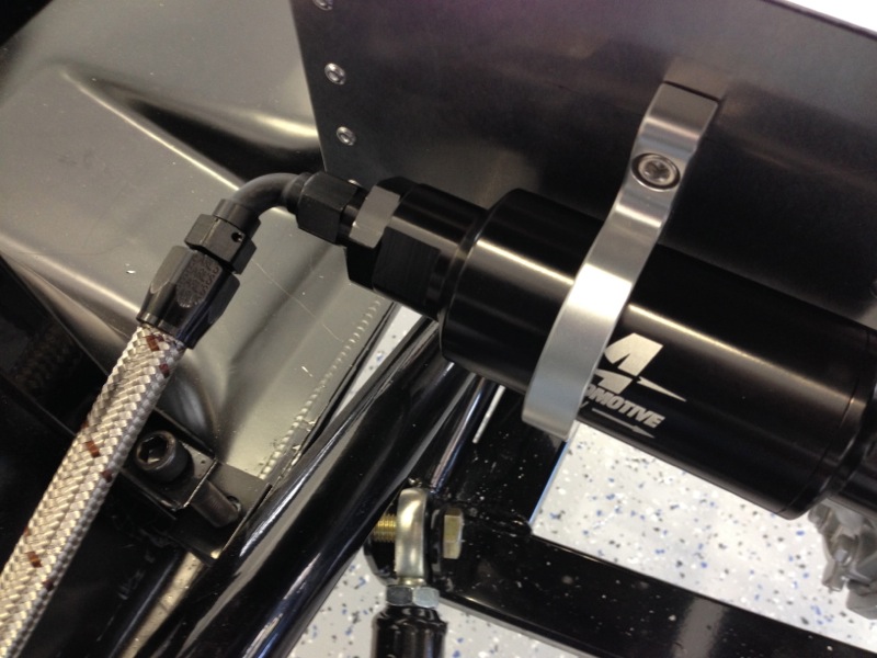
The hose on the left in the pic below is other end of the top hose in the pic above and goes into the fuel filter.
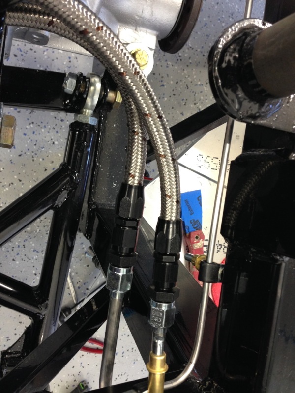
And in this final pic the hoses connect to the hard lines going to the engine bay. The one on the right is the return line and therefore the one on the left is the supply line coming from the other side of the fuel filter.
Ok that’s it for now. This weekend I’ll start prepping the engine for install. Looking forward to things like mounting the clutch, pressure plate, bellhousing and transmission. Should be fun.
The coolest thing about this project is checking out the tools Randy has some how been able to convince Caroline he “needs”…
Good point, Randy how many specialty tools have you or are you picking up?
I can assure you that all the tools I’ve added to the collection are “needed”
Good question on the tools. I’ve talked about some of them on different posts but here is a list of what I have acquired so far. This list will be what I consider beyond what you would normally find in someones tool box. So even though I’ve added some new wrenches and sockets I won’t count those.
Torque wrench – Both inch pounds and foot pounds
Flaring tools – 45 and 37 degree
Tubing Bender
Koul Tool – to help assemble braided hoses
AN-6 Wrench – Special aluminum wrench for AN fittings, reduces marks on the anodized coating
Clutch Alignment tool – Helps align the clutch disc in the center of the flywheel and pressure plate
Engine Hoist – Obvious
Engine Leveler – Connects to hoist and helps adjust the angle of the engine during install/removal
Clecos – You’ve seen this when I was working the sheetmetal
Angle grinder – Air tool with an abrasive cut off wheel
Die Grinder – Air tool with an abrasive sanding disc
Stepped drill bits – Multi size stepped drill bit
That’s about it for now or at least all I can think of.
I will probably add, ok I will add, a special crimper when I do the wiring. The WeatherPack connectors will need the crimper.
So Randy, I am curious, are you using an iPhone for the pictures or some other digital camera? The tools for the hose assembly are quite cool and looks like it really does insure that the hose to fitting are assembled correctly by providing a way to index the pushback distance of the hose in the assembly process.
I can already hear the awesome motor roaring now!
The majority of the pics I’ve been taking with my iPhone. It’s just the most convenient and with the Photo Stream I can easily pull the pics in and edit them for posting.